
Products · Perforated
Perforated Cable Tray
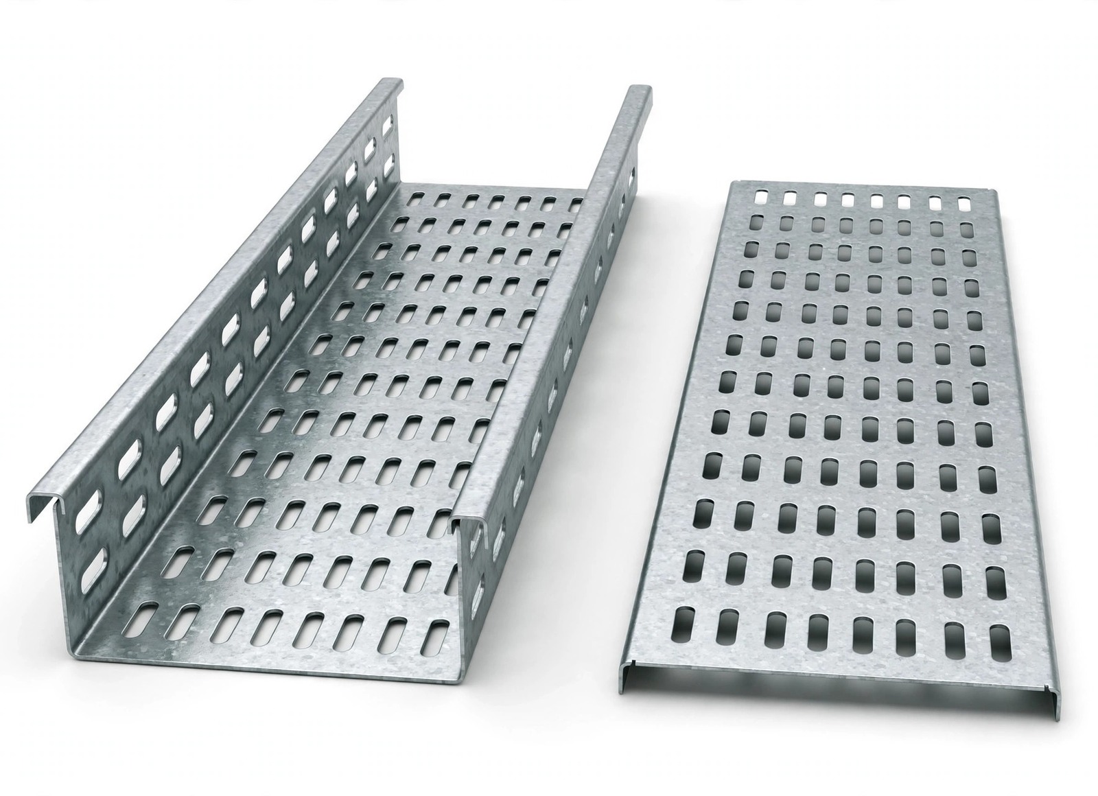
Ventilated trough tray with punched slots for heat dissipation, drainage and easy cable tie-down
Ventilated trough tray with punched slots for heat dissipation and easy cable tie-down — the workhorse for power distribution, control cabling and building services. Our P1–P6 series is roll-formed and punched on automatic lines, with the P1 per-model safe-working-load (SWL) and weight table published in the catalog.
 1 / 4
Technical Drawings & Dimensions
Schematic diagrams below show the perforated-tray structure and the parameters that define a size. They are schematics only — not to scale, not engineering drawings, and not CAD drawings. Do not use them as fabrication drawings; model-specific dimensions are cited from the catalog table in your quotation.
Verified parameters
| Series | P1–P6 (perforated trough); full SWL table published for P1 only (catalog p.056) |
|---|---|
| Width (W) | 50–1200 mm |
| Side height (H) | 10–200 mm (standard tables 25–200 mm) |
| Thickness (T) | 0.5–3.0 mm |
| Tolerances | Raw material ±0.05 mm · finished size ±2 mm |
| Published table | P1 straight sections, catalog p.056; load–span curves, catalog p.054 |
Covers are available as an option; cover size and material match are confirmed with your quotation — the catalog publishes no separate cover parameter table.
Configure Your Cable Tray
Pick a style, material and finish — the configurator only offers combinations the published data supports, and your selection is written into the inquiry form at the bottom of the page (you can still edit it there).
Need a Custom Size?
Standard sizes ship from regular production; custom widths, heights and colours are made to order. Trays are bundled, film-wrapped and palletised for export, with fittings counted and packed in the same shipment. Custom widths, heights and colors are made to order and confirmed in your quotation — send your BOQ or drawings with the inquiry below (PDF, Excel, DWG or ZIP).
Technical Specifications
General Specifications
| Series | P1–P6 (perforated trough); full SWL table published for P1 only |
|---|---|
| Width | 50–1200 mm |
| Side height | 10–200 mm (standard tables 25–200 mm) |
| Thickness | 0.5–3.0 mm |
| Materials | Q235 steel · stainless 201 / 304 / 316 · aluminum 6061-T6 / 6063-T5 |
| Finishes | Electro-galvanized (zinc 8–25 µm) · pre-galvanized 40 / 80 / 275 g/m² · hot-dip galvanized 45 / 65 / 85 µm · ZAM · powder coated |
| Tolerances | Raw material ±0.05 mm · finished size ±2 mm |
Ranges from the Hongfeng product catalog parameter tables. Exact model tables (SWL / weight per size) are sent with your quotation.
Load Data & Installation Conditions
Safe working loads are published per model and size in the catalog P1 table below (prepared to DIN EN IEC 61537 load–span curves, catalog p.054). For P2–P6 styles, SWL and unit weight are confirmed with your quotation — the size grid, materials and finishes are the same as P1.
SWL values are the catalog P1 table values (p.056), in N/m, with load–span curves prepared to DIN EN IEC 61537 (catalog p.054). Conditions beyond the table are confirmed with your quotation; one size's SWL is never a promise for the whole series.
Available Configurations
- Punched ventilation slots dissipate heat and accept cable ties anywhere along the run
- Published P1 model table — e.g. P1 series 300×100 mm at 215 N/m SWL (catalog p.056)
- Slot dimensions and patterns vary by tray size and type, per the catalog note — no single hole size is claimed for the whole range
- Finished size tolerance ±2 mm, so lengths and fittings align on site without rework
Model table — P1 straight sections
Published sizes with safe working load (SWL) and unit weight. Filter by style, width and height — the configurator selection filters this table automatically.
| Style | Width (mm) | Height (mm) | SWL (N/m) | Weight (kg/m) |
|---|---|---|---|---|
| P1 | 50 | 25 | 7.8 | 0.80 |
| P1 | 60 | 25 | 9.2 | 0.87 |
| P1 | 60 | 40 | 36.8 | 1.07 |
| P1 | 60 | 50 | 70.8 | 1.20 |
| P1 | 80 | 40 | 49.1 | 1.20 |
| P1 | 80 | 50 | 94.6 | 1.33 |
| P1 | 80 | 60 | 128 | 1.47 |
| P1 | 100 | 50 | 110 | 1.76 |
| P1 | 100 | 60 | 135 | 1.92 |
| P1 | 100 | 80 | 145 | 2.24 |
| P1 | 100 | 100 | 171 | 2.56 |
| P1 | 150 | 50 | 118 | 2.70 |
| P1 | 150 | 60 | 141 | 2.90 |
| P1 | 150 | 80 | 157 | 3.30 |
| P1 | 150 | 100 | 182 | 3.70 |
| P1 | 200 | 50 | 123 | 3.20 |
| P1 | 200 | 60 | 148 | 3.40 |
| P1 | 200 | 80 | 168 | 3.80 |
| P1 | 200 | 100 | 196 | 4.20 |
| P1 | 200 | 150 | 215 | 5.20 |
| P1 | 250 | 50 | 129 | 3.70 |
| P1 | 250 | 60 | 156 | 3.90 |
| P1 | 250 | 80 | 182 | 4.30 |
| P1 | 250 | 100 | 209 | 4.70 |
| P1 | 250 | 150 | 235 | 5.70 |
| P1 | 300 | 50 | 131 | 4.20 |
| P1 | 300 | 60 | 165 | 4.40 |
| P1 | 300 | 80 | 198 | 4.80 |
| P1 | 300 | 100 | 215 | 5.20 |
| P1 | 300 | 150 | 246 | 6.21 |
| P1 | 300 | 200 | 268 | 7.21 |
| P1 | 400 | 50 | 138 | 6.94 |
| P1 | 400 | 60 | 170 | 7.21 |
| P1 | 400 | 80 | 205 | 7.74 |
| P1 | 400 | 100 | 226 | 8.27 |
| P1 | 400 | 150 | 259 | 9.61 |
| P1 | 400 | 200 | 276 | 10.94 |
| P1 | 500 | 60 | 181 | 8.54 |
| P1 | 500 | 80 | 215 | 9.07 |
| P1 | 500 | 100 | 231 | 9.61 |
| P1 | 500 | 150 | 265 | 10.94 |
| P1 | 500 | 200 | 289 | 12.28 |
| P1 | 600 | 80 | 225 | 10.41 |
| P1 | 600 | 100 | 268 | 10.94 |
| P1 | 600 | 150 | 289 | 12.28 |
| P1 | 600 | 200 | 301 | 13.61 |
| P1 | 800 | 100 | 279 | 17.01 |
| P1 | 800 | 150 | 308 | 18.68 |
| P1 | 800 | 200 | 335 | 20.35 |
Source: Hongfeng product catalog p.056 (P1 straight sections, catalog numbers HF-A-P1-01A series). Load–span curves prepared to DIN EN IEC 61537 (catalog p.054). Raw material tolerance ±0.05 mm; finished size tolerance ±2 mm.
The catalog publishes the full SWL table for P1 only. For P2–P6 styles, SWL and unit weight are confirmed with your quotation — the size grid, materials and finishes are the same. Tell us the style in the inquiry and Jason will cite the table used.
Materials & Surface Finishes
Available for this product family (widths 50–1200 mm, heights 10–200 mm, thickness 0.5–3.0 mm). Exact availability per material–finish combination is confirmed with your quotation; final selection depends on the project environment.
Materials
Q235 steel
Carbon steel — the standard tray material.
Stainless 201
Stainless grade for indoor and mildly corrosive environments.
Stainless 304
Stainless grade for corrosive environments.
Stainless 316
Stainless grade for highly corrosive environments.
Aluminum 6061-T6
Lightweight aluminum alloy.
Aluminum 6063-T5
Lightweight aluminum alloy.
Surface Finishes
Electro-galvanized
Zinc 8–25 µm
Zinc coating applied by electro-galvanizing.
Pre-galvanized
40 g/m²
Zinc-coated sheet, commonly specified for indoor and dry environments.
Pre-galvanized
80 g/m²
Zinc-coated sheet, commonly specified for indoor and dry environments.
Pre-galvanized
275 g/m²
Zinc-coated sheet, commonly specified for indoor and dry environments.
Hot-dip galvanized
45 µm
Hot-dip coating, commonly specified for outdoor and harsh environments.
Hot-dip galvanized
65 µm
Hot-dip coating, commonly specified for outdoor and harsh environments.
Hot-dip galvanized
85 µm
Hot-dip coating, commonly specified for outdoor and harsh environments.
ZAM
Zinc-aluminum-magnesium coating
Coated steel for corrosive environments.
Powder coated
Color customizable
Coated finish in custom colors.
Perforated Cable Tray Fittings & Accessories
Horizontal tees (HT) and horizontal crosses (HC), 90° / 60° / 45° / 30° horizontal elbows (HE), vertical internal bends (VIB) and vertical external bends (VEB), plus left, right and middle reducers (LR / RR / MR). Tee and cross dimensions are calculated on R300 (catalog p.057); other heights, radii and finishes are available. Covers are available as an option; cover size and material match are confirmed with your quotation — the catalog publishes no separate cover parameter table.
Also available for this tray
- HT — Horizontal tees: Tee branches off a straight perforated run.
- HC — Horizontal crosses: Four-way branch for perforated runs.
- HE — Horizontal elbows 90° / 60° / 45° / 30°: Direction changes in the horizontal plane.
- VIB — Vertical internal bends: Up / down direction changes on the inside of the run.
- VEB — Vertical external bends: Up / down direction changes on the outside of the run.
- LR / RR / MR — Reducers: Left, right and middle reducers between tray widths.
Where It Is Used
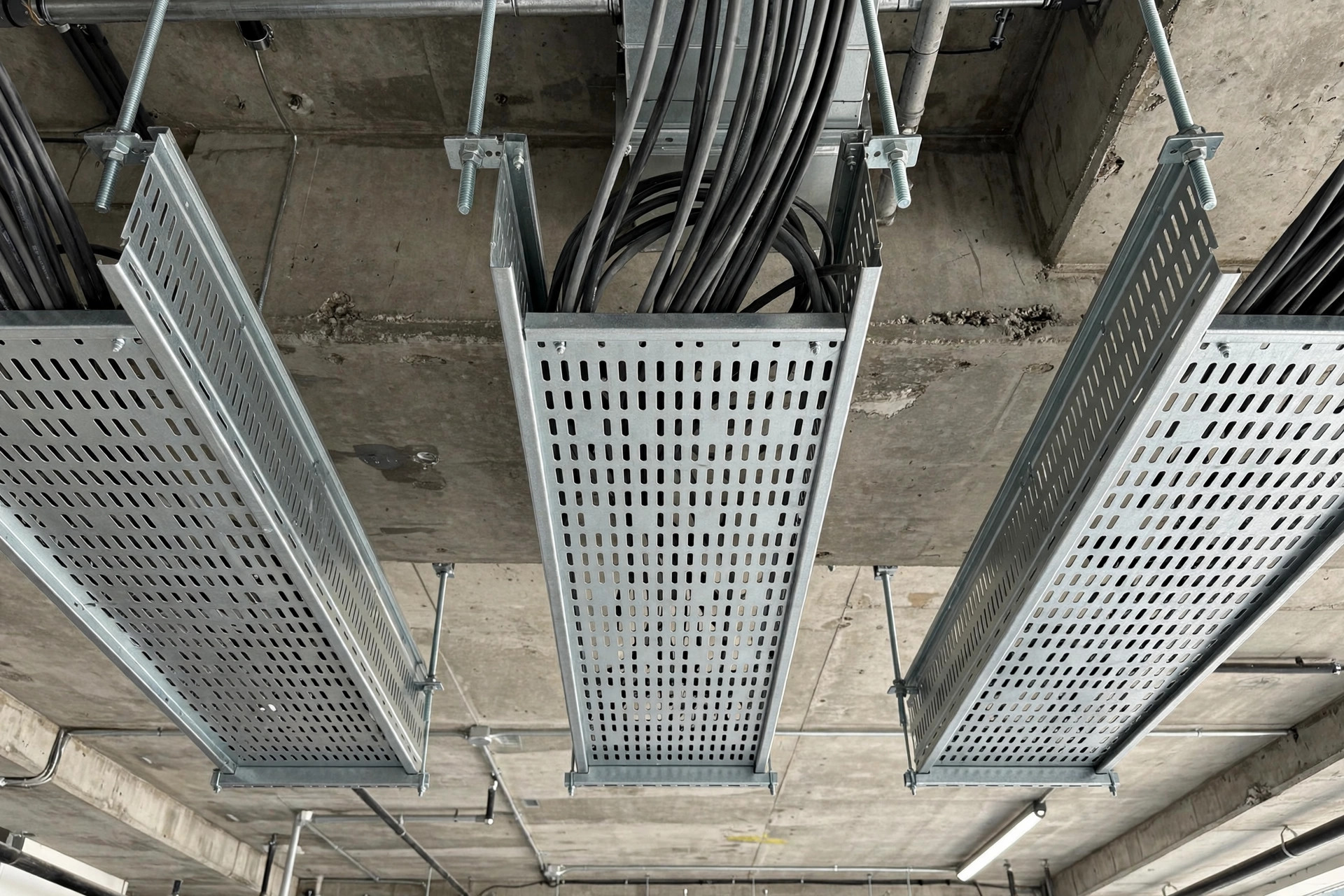
Building power distribution & building services
General power and control cable runs where punched slots ventilate the cables and accept cable ties anywhere along the run.

Plant & pipe-rack power routes
The standard tray for power distribution, control cabling and building services on general industrial routes.
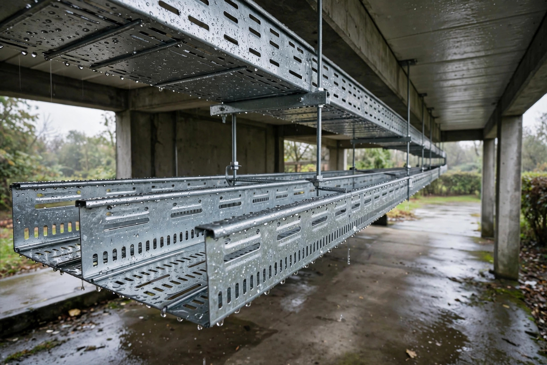
Damp or semi-outdoor routes needing drainage
The punched slots double as drainage openings; the finish for a corrosive environment is still confirmed separately against the material-selection guide.
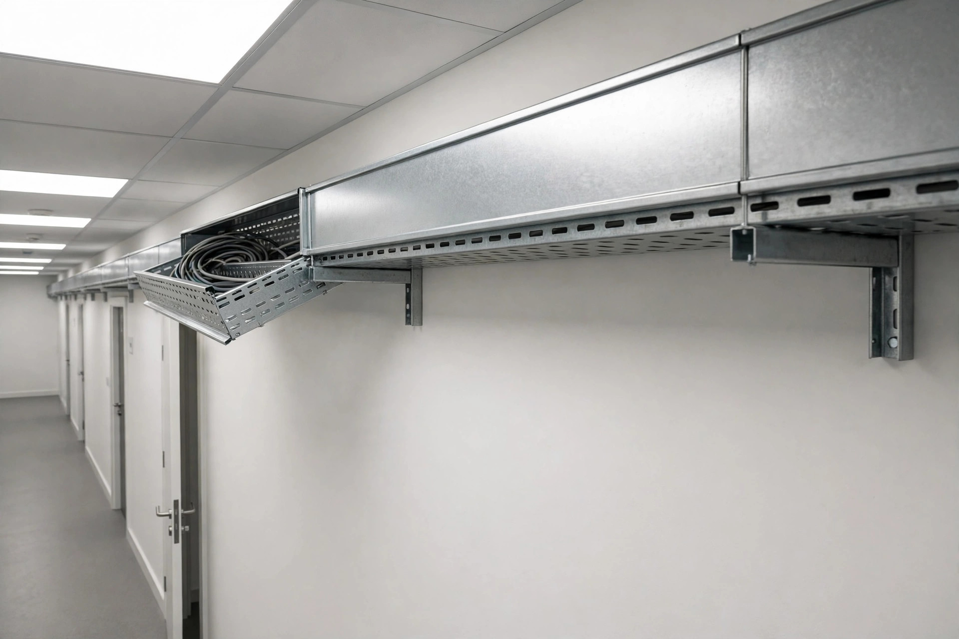
Indoor runs with covers
Cover option available for enclosed indoor runs; cover size and material match are confirmed with your quotation.
Application images are illustrative. Actual project specifications and installations may vary.
Manufacturing & Quality Control
Factory-direct supply from Liaocheng, Shandong — 50,000 m² site, 300 staff. The photos below show factory production and finishing areas; they illustrate the manufacturing environment and are not claimed to be a perforated-only line.
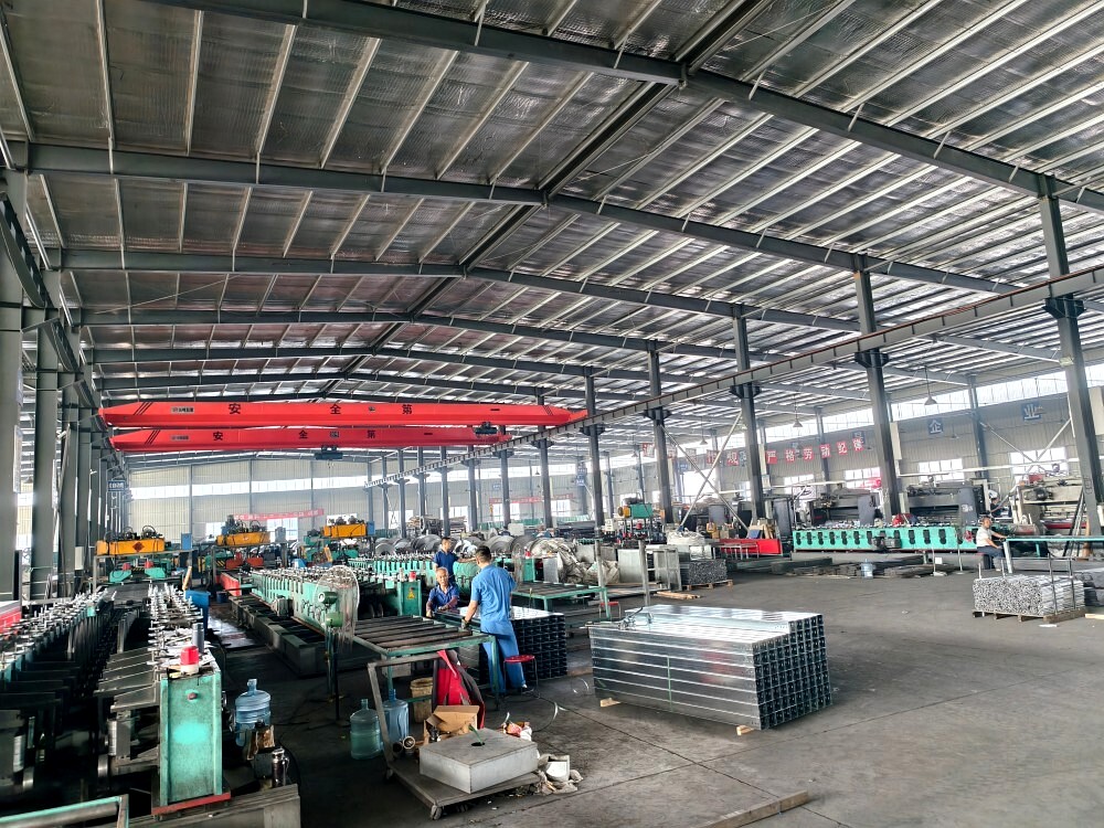
Forming lines and finished sections in the production hall.
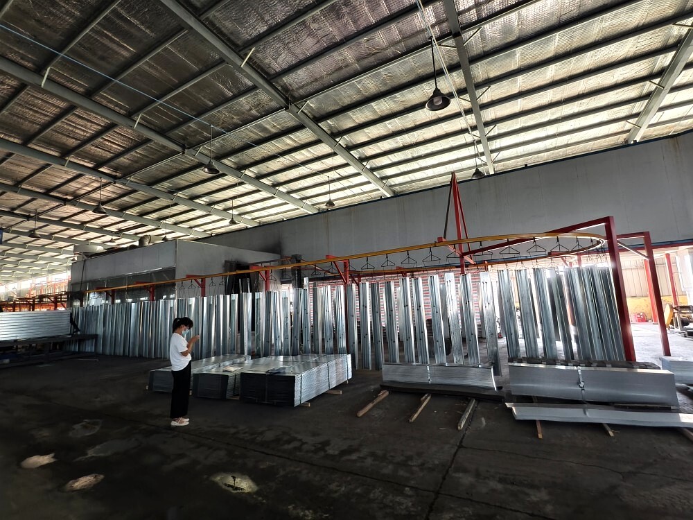
Coating and finishing area for galvanized and coated sections.
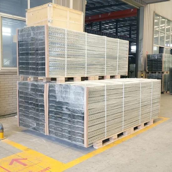
Film-wrapped, palletised sections for export shipment.
Material tolerance ±0.05 mm.
Roll-formed and punched on automatic lines — slots in the base and side walls.
Electro-galvanized, pre-galvanized, hot-dip galvanized, ZAM and powder coated finishes.
Dimensional checks to ±2 mm finished-size tolerance.
Bundled, film-wrapped and palletised for export, with fittings counted and packed in the same shipment.
Quality Documents
- ISO 9001:2015 — Guang Hui, certificate GH005-2023Q0022
- ISO 14001:2015 — Guang Hui, certificate GH005-2023E0015
- ISO 45001:2018 — Guang Hui, certificate GH005-2023S0015
- UDEM Attestation of Conformity, Low Voltage Directive 2014/35/EU, EN 61537:2007, No. M.2023.206.C88198 — model HF01A only
- JB/T 10216-2013 sample type-test reports — samples only, not a series-wide certification
Frequently Asked Questions
Can I order a size that is not in the P1 table?
Yes. The catalog customization ranges are widths 50–1200 mm, heights 10–200 mm and thicknesses 0.5–3.0 mm, and customized drawings are accepted. The exact size is confirmed with your quotation.
Where is the load table for P2–P6?
The catalog publishes the full table for P1 only. SWL and unit weight for P2–P6 are confirmed with your quotation, which will state the table used.
Which finishes are available for perforated tray?
Pre-galvanized 40 / 80 / 275 g/m², hot-dip galvanized 45 / 65 / 85 µm, ZAM, and powder coated (color customizable) — catalog p.056.
What about MOQ, custom lead time and cover matching?
All confirmed with your quotation. The catalog publishes no separate cover parameter table, so cover size and material match are confirmed case by case.
What information is required for a quotation?
Style, material, finish, width, height, thickness and quantity — plus the project environment if finish selection matters. Use the configurator above and the inquiry form sends your selection automatically.
Can I submit a BOQ or technical drawing?
Yes — attach PDF, Excel, DWG or ZIP in the inquiry form below, or email the file to jasonzuo@cabletraysystem.com if the upload fails.
What affects the production lead time?
Size, material, finish, quantity and current production scheduling. Lead time is confirmed with your quotation — it is not fixed on this page.
Get a Project Quote
Request a Quote — Perforated Cable Tray
Tell us sizes, finish and quantity — or attach your BOQ. Jason replies personally with a priced offer.