
Products · Support
Strut Channel (C Channel)
41 mm metal-framing channel for trapeze hangers, wall brackets and support frames
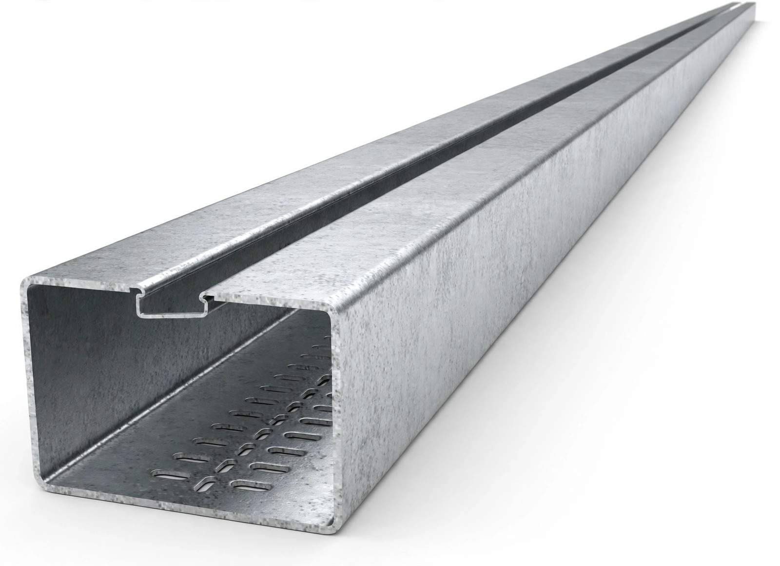
The 41 mm metal-framing channel that carries the tray runs — trapeze hangers, wall brackets and support frames for cable tray, pipework and equipment. Our catalog C-channel range covers 41×21 and 41×41 single profiles plus welded back-to-back doubles, in slotted and plain versions, with the brackets, hanging supports and spring-nut fittings of the same support system.
 1 / 2
Technical Drawings & Dimensions
Schematic diagrams below show the single C profile and the back-to-back double, and the parameters that define a profile. They are schematics only — not to scale, not engineering drawings, and not CAD drawings. Do not use them as fabrication drawings; model-specific dimensions are cited from the catalog table in your quotation.
Verified parameters
| Profiles | 41×21 mm (C 2141) · 41×41 mm (C 4141) · welded doubles 42×41 mm (C 4241) & 83×41 mm (C 8341) |
|---|---|
| Versions | Slotted (A) · plain · 3-side perforated (C 4141B, 41×41 only) |
| Slot size | 14×25 mm at 50 mm pitch (slotted versions) |
| Thickness | 1.2–2.5 mm by profile — 41×21 from 1.2 mm · 41×41 in 1.5 / 2.0 / 2.5 mm · doubles in 2.0 / 2.5 mm |
| Lengths | 3,000 mm standard · 6,000 mm in hot-dip galvanized |
| Weight | 0.85–5.50 kg/m by profile & thickness — e.g. C 4141A at 1.55–2.58 kg/m |
| Allowable bending stress | 21.82 kN/cm² (published per profile in the catalog, with moment of inertia and section modulus) |
Spring channel nuts grip the inturned, serrated edges and fit the slot — fittings can be placed anywhere along the slot and repositioned without drilling.
Configure Your Cable Tray
Pick a style, material and finish — the configurator only offers combinations the published data supports, and your selection is written into the inquiry form at the bottom of the page (you can still edit it there).
Need a Custom Size?
Channels are bundled and strapped in standard lengths; brackets, spring nuts, threaded rods and fittings are counted into the same shipment as your trays, so the support kit lands together with the run it carries. Custom sizes are made to order and confirmed in your quotation — send your BOQ or drawings with the inquiry below (PDF, Excel, DWG or ZIP).
Technical Specifications
General Specifications
| Profiles | 41×21 mm (C 2141) · 41×41 mm (C 4141) · welded doubles 42×41 mm (C 4241) & 83×41 mm (C 8341) |
|---|---|
| Versions | Slotted (A) · plain · 3-side perforated (C 4141B, 41×41 only) |
| Slot size | 14×25 mm at 50 mm pitch (slotted versions) |
| Thickness | 1.2–2.5 mm by profile — 41×21 from 1.2 mm · 41×41 in 1.5 / 2.0 / 2.5 mm · doubles in 2.0 / 2.5 mm |
| Lengths | 3,000 mm standard · 6,000 mm in hot-dip galvanized |
| Finishes | Pre-galvanized · hot-dip galvanized |
| Weight | 0.85–5.50 kg/m by profile & thickness — e.g. C 4141A at 1.55–2.58 kg/m |
| Section data | Moment of inertia, section modulus and allowable bending stress (21.82 kN/cm²) published per profile in the catalog |
Profile, version, slot, thickness, length, finish and weight ranges from the Hongfeng product catalog. Span safe loads are catalog p.125 (detailed tables below); section data is published per profile in the catalog and is stated here as text only, not tabulated per profile.
Load Data & Installation Conditions
Support selection is a load decision too. The catalog safe-load tables below (p.125) give, for each profile and thickness, the uniform load q and the concentrated allowable load F at spans from 500 to 3000 mm, at a maximum deflection of L/200. Spans the catalog leaves blank have no published value — they are confirmed with your quotation, never interpolated. The catalog does not state whether q is per metre or total, or a safety factor beyond the deflection limit, so the quotation will state the table used.
Span safe-load tables are catalog p.125, published as two separate tables: uniform load q and concentrated allowable load F — do not mix the two. Maximum deflection L/200. Spans the catalog leaves blank have no published value and are confirmed with your quotation, never interpolated. The catalog does not state whether q is per metre or total, so the quotation will state the table used.
Available Configurations
- 41 mm framing system: 41×21 and 41×41 single channels, plus welded doubles 42×41 and 83×41 for heavier trapeze and frame loads
- Slotted versions punched with 14×25 mm slots at 50 mm pitch; plain and 3-side perforated versions in the same profile family
- Spring channel nuts grip the inturned, serrated edges — fittings can be placed anywhere along the slot and repositioned without drilling (catalog: Metal Framing – 41 mm)
- Safe loads published by span in the catalog (p.125) at a maximum deflection of L/200 — pick profile, thickness and span, then read q or F off the table
Profiles — C channel
This grid lists profile section sizes only (width × height) — it carries no SWL or weight values. For safe loads by span, read the detailed tables below (catalog p.125, maximum deflection L/200). Filter by profile, width and height — the configurator selection filters this table automatically.
| Style | Width (mm) | Height (mm) | SWL (N/m) | Weight (kg/m) |
|---|---|---|---|---|
| 41×21 (C 2141) | 41 | 21 | — | — |
| 41×41 (C 4141) | 41 | 41 | — | — |
| 42×41 welded double (C 4241) | 42 | 41 | — | — |
| 83×41 welded double (C 8341) | 83 | 41 | — | — |
Source: Hongfeng product catalog, Metal Framing – 41 mm chapter. Span safe-load tables are catalog p.125 (see the detailed tables below).
This profile grid lists section sizes only — safe loads by span are in the detailed tables below (catalog p.125, maximum deflection L/200). SWL and unit weight for your profile, thickness and span are confirmed with your quotation.
Safe-load tables — by span
Catalog safe loads at a maximum deflection of L/200, where L is the support spacing (span). Blank cells are spans the catalog leaves unpublished — they are left blank, never interpolated. Use the uniform-load table for distributed loads and the concentrated-load table for a mid-span point load; do not mix the two.
Uniform load q (kN)
| Span L (mm) | Max deflection L/200 (mm) | 21×41 · 1.5 mm | 21×41 · 2.0 mm | 21×41 · 2.5 mm | 42×41 · 1.5 mm | 42×41 · 2.0 mm | 42×41 · 2.5 mm | 41×41 · 1.5 mm | 41×41 · 2.0 mm | 41×41 · 2.5 mm | 83×41 · 1.5 mm | 83×41 · 2.0 mm | 83×41 · 2.5 mm |
|---|---|---|---|---|---|---|---|---|---|---|---|---|---|
| 500 | 2.50 | 2.2 | 2.8 | 3.3 | 6.3 | 8.19 | 9.9 | 5.8 | 7.8 | 9.6 | 14.5 | 19.5 | 24 |
| 750 | 3.75 | 1 | 1.35 | 1.5 | 3 | 3.8 | 4.8 | 2.8 | 3.6 | 4.59 | 8.6 | 10.8 | 13.9 |
| 1000 | 5.00 | 0.56 | 0.7 | 0.8 | 1.7 | 2.1 | 2.6 | 1.6 | 2 | 2.5 | 4.8 | 6.2 | 7.7 |
| 1250 | 6.25 | 0.36 | 0.45 | 0.53 | 1.14 | 1.5 | 1.8 | 1.1 | 1.4 | 1.7 | 3.1 | 3.9 | 5 |
| 1500 | 7.50 | 0.25 | 0.31 | 0.37 | 0.95 | 1.12 | 1.35 | 0.9 | 1.1 | 1.3 | 2.4 | 3 | 3.8 |
| 1750 | 8.75 | 0.18 | 0.23 | 0.27 | 0.74 | 0.95 | 1.1 | 0.7 | 0.9 | 1.1 | 1.8 | 2.4 | 3 |
| 2000 | 10.00 | 0.12 | 0.17 | 0.21 | 0.6 | 0.75 | 0.8 | 0.55 | 0.7 | 0.8 | 1.4 | 2.1 | 2.6 |
| 2250 | 11.25 | — | 0.12 | 0.16 | 0.5 | 0.62 | 0.75 | 0.45 | 0.6 | 0.7 | 1.2 | 1.7 | 2.29 |
| 2500 | 12.50 | — | 0.1 | 0.12 | 0.42 | 0.52 | 0.65 | 0.4 | 0.5 | 0.62 | 1 | 1.4 | 1.8 |
| 2750 | 13.75 | — | — | — | 0.37 | 0.45 | 0.6 | 0.36 | 0.44 | 0.56 | 0.8 | 1.2 | 1.6 |
| 3000 | 15.00 | — | — | — | 0.33 | 0.4 | 0.5 | 0.32 | 0.4 | 0.5 | 0.7 | 1 | 1.4 |
Concentrated allowable load F (kN)
| Span L (mm) | Max deflection L/200 (mm) | 21×41 · 1.5 mm | 21×41 · 2.0 mm | 21×41 · 2.5 mm | 42×41 · 1.5 mm | 42×41 · 2.0 mm | 42×41 · 2.5 mm | 41×41 · 1.5 mm | 41×41 · 2.0 mm | 41×41 · 2.5 mm | 83×41 · 1.5 mm | 83×41 · 2.0 mm | 83×41 · 2.5 mm |
|---|---|---|---|---|---|---|---|---|---|---|---|---|---|
| 500 | 2.50 | 0.65 | 0.7 | 0.8 | 1.7 | 2.1 | 2.6 | 1.6 | 2 | 2.5 | 4.8 | 6.2 | 7.7 |
| 750 | 3.75 | 0.5 | 0.56 | 0.6 | 1.2 | 1.5 | 1.8 | 1.1 | 1.4 | 1.7 | 3.2 | 4.09 | 5.2 |
| 1000 | 5.00 | 0.35 | 0.38 | 0.42 | 0.82 | 1.1 | 1.35 | 0.8 | 1 | 1.3 | 2.4 | 3.1 | 3.9 |
| 1250 | 6.25 | 0.24 | 0.28 | 0.35 | 0.6 | 0.82 | 1.05 | 0.6 | 0.8 | 1 | 1.9 | 2.4 | 3.1 |
| 1500 | 7.50 | 0.19 | 0.23 | 0.3 | 0.52 | 0.74 | 0.85 | 0.5 | 0.7 | 0.8 | 1.6 | 2 | 2.6 |
| 1750 | 8.75 | 0.15 | 0.2 | 0.24 | 0.45 | 0.6 | 0.74 | 0.42 | 0.57 | 0.7 | 1.4 | 1.8 | 2.2 |
| 2000 | 10.00 | — | 0.15 | 0.18 | 0.4 | 0.45 | 0.65 | 0.38 | 0.44 | 0.6 | 1.1 | 1.5 | 1.9 |
| 2250 | 11.25 | — | — | — | 0.35 | 0.42 | 0.55 | 0.35 | 0.4 | 0.55 | 0.9 | 1.2 | 1.7 |
| 2500 | 12.50 | — | — | — | 0.31 | 0.4 | 0.52 | 0.3 | 0.38 | 0.5 | 0.7 | 1.1 | 1.5 |
| 2750 | 13.75 | — | — | — | 0.25 | 0.34 | 0.45 | 0.25 | 0.33 | 0.45 | 0.6 | 0.9 | 1.4 |
| 3000 | 15.00 | — | — | — | 0.2 | 0.3 | 0.4 | 0.2 | 0.3 | 0.4 | 0.5 | 0.8 | 1.2 |
Source: Hongfeng product catalog p.125 (C Support Static Values — Safe Load). Profile codes: 21×41 = C 2141A, 42×41 = C 4241A, 41×41 = C 4141A, 83×41 = C 8341A; trailing 15 / 20 / 25 = 1.5 / 2.0 / 2.5 mm thickness. The catalog does not state whether q is per metre or total — the quotation will state the table used. Spans the catalog leaves blank (—) are confirmed with your quotation, never interpolated.
Materials & Surface Finishes
Available for this product family: steel channel in pre-galvanized and hot-dip galvanized finishes. Exact availability per profile–finish combination is confirmed with your quotation.
Materials
Steel
Channel material for the 41 mm framing range.
Surface Finishes
Pre-galvanized
Standard length 3,000 mm
Pre-galvanized finish for the 41 mm framing range.
Hot-dip galvanized
Standard length 3,000 mm · 6,000 mm in hot-dip galvanized
Hot-dip galvanized finish for the 41 mm framing range.
Strut Channel Fittings & Accessories
C Channel Adjustable Brace Fitting Bases (CDB-23 / CDB-24, hot-dip galvanized to TS-EN ISO 1461:2011), C Channel Spring Nuts (NYS-NS series, electro-galvanized; stainless 304L / 316L available) and Fixing Bolts (NTS series), Plastic End Caps (END 4141 / END 4121, PVC), Support Hanger Clamps (PAM-1 / PAM-2 / PAM-3, die cast — PAM safe working loads 1.10 / 2.40 / 3.10 kN), DIN 975 Threaded Rods (TM series, M6 / M8 / M10 / M12, 500 / 1000 / 2000 / 3000 mm, electro-galvanized) and DIN 9300 Couplers and Head Plates (TUS series, M6–M12) — catalog pp.123–124, plus the p.126 mounting-and-fastener range.
Also available for this tray
- CDB-23 / CDB-24 — Adjustable brace fitting bases: Hot-dip galvanized to TS-EN ISO 1461:2011.
- NYS-NS — C channel spring nuts: Electro-galvanized; stainless 304L / 316L nut option available.
- NTS — Fixing bolts: Fixing bolts for the C channel range.
- END 4141 / END 4121 — Plastic end caps: PVC end caps for the channel range.
- PAM-1 / PAM-2 / PAM-3 — Support hanger clamps: Die-cast clamps; PAM safe working loads 1.10 / 2.40 / 3.10 kN.
- TM — DIN 975 threaded rods: M6 / M8 / M10 / M12, 500 / 1000 / 2000 / 3000 mm, electro-galvanized.
- TUS — DIN 9300 couplers and head plates: Couplers and head plates, M6–M12.
Where It Is Used
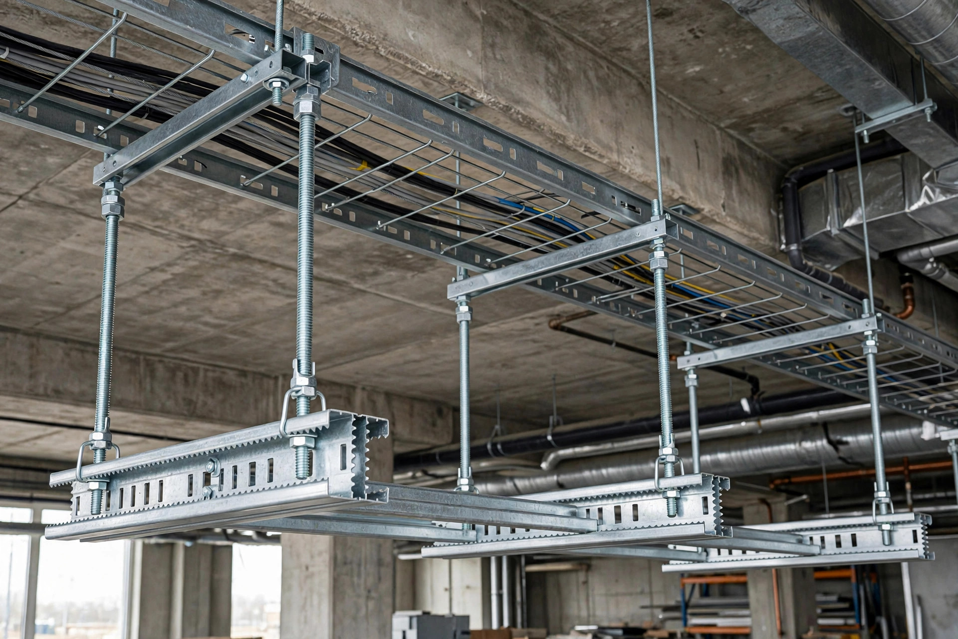
Tray hangers & cantilever brackets
Trapeze hangers, wall brackets and support frames carrying tray runs, pipework and equipment — sized off the span tables above.
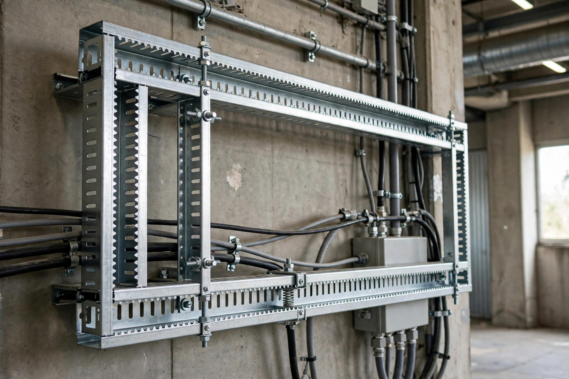
41 mm framing systems
Spring nuts locate anywhere along the slot without drilling and can be repositioned — the frame adapts when the layout changes.
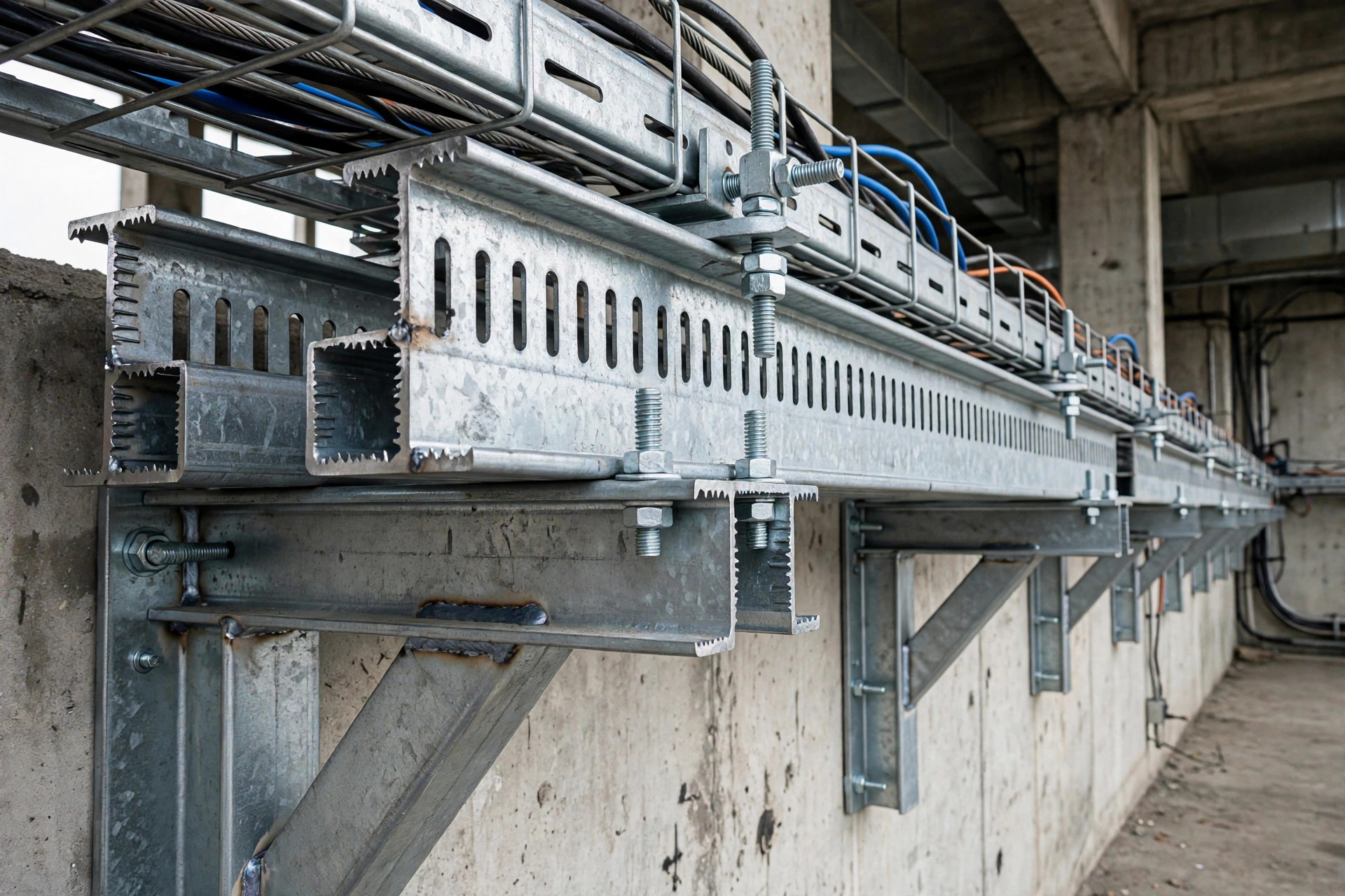
Heavy brackets & frames
Welded back-to-back doubles (42×41 / 83×41) for heavier cantilever brackets and frame loads; read their columns in the tables above.
Shipped with your trays
Brackets, hanger rods, spring nuts and fittings are counted into the same shipment as the trays they support.
Application images are illustrative. Actual project specifications and installations may vary.
Manufacturing & Quality Control
Factory-direct supply from Liaocheng, Shandong — 50,000 m² site, 300 staff. The photos below show factory production and finishing areas; they illustrate the manufacturing environment and are not claimed to be a strut-only line.
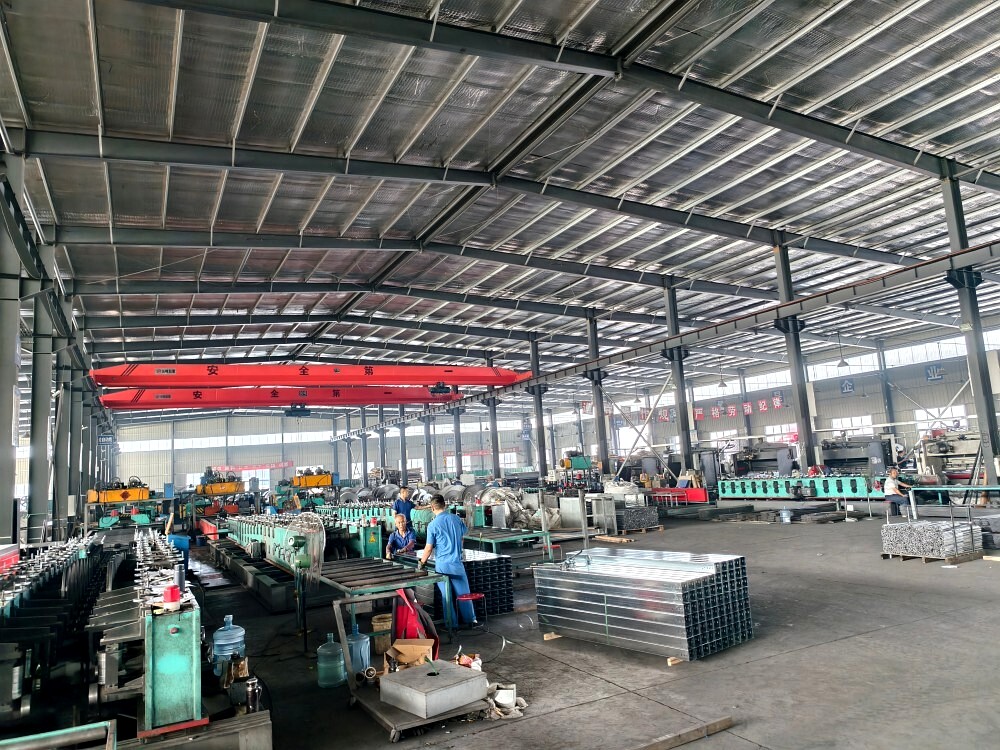
Forming lines and finished sections in the production hall.
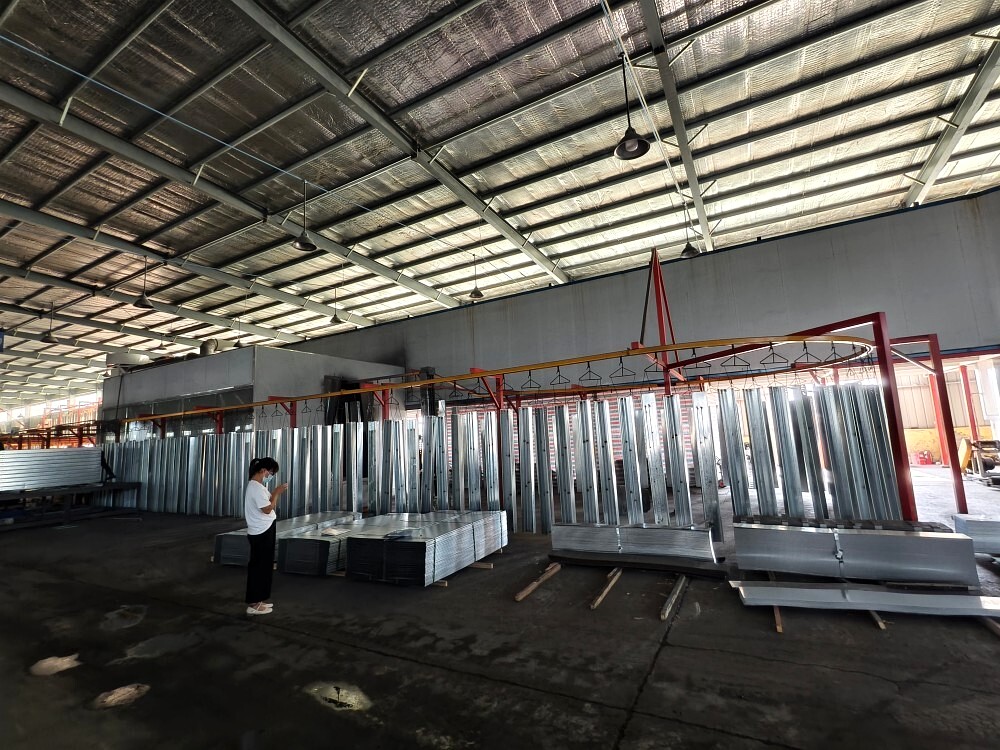
Coating and finishing area for galvanized and coated sections.
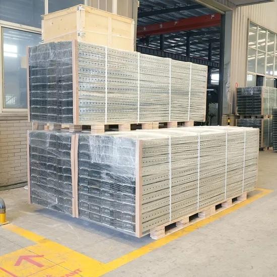
Film-wrapped, palletised sections for export shipment.
Steel for the 41 mm framing range.
Channels formed to profile; slotted versions punched with 14×25 mm slots at 50 mm pitch, plain and 3-side perforated versions in the same family.
Pre-galvanized or hot-dip galvanized finish.
Profile, thickness and finish checked before packing; span loads read from catalog p.125.
Bundled and strapped in standard lengths; brackets, spring nuts, threaded rods and fittings counted into the same shipment as your trays.
Quality Documents
- ISO 9001:2015 — Guang Hui, certificate GH005-2023Q0022
- ISO 14001:2015 — Guang Hui, certificate GH005-2023E0015
- ISO 45001:2018 — Guang Hui, certificate GH005-2023S0015
- UDEM Attestation of Conformity, Low Voltage Directive 2014/35/EU, EN 61537:2007, No. M.2023.206.C88198 — model HF01A only
- JB/T 10216-2013 sample type-test reports — samples only, not a series-wide certification
Frequently Asked Questions
How much can a strut channel carry?
Read it off catalog p.125: pick the profile (21×41 / 42×41 / 41×41 / 83×41) and thickness (1.5 / 2.0 / 2.5 mm), then read q (uniform load) or F (concentrated load) at your support spacing L, at a maximum deflection of L/200. Spans the catalog leaves blank are confirmed with your quotation.
What is the difference between q and F?
q is the uniform (distributed) load and F is the concentrated allowable load — the catalog publishes them as two separate tables. Select from the table that matches how the load actually acts; do not mix the two.
Slotted or plain — which do I choose?
Slotted versions are punched with 14×25 mm slots at 50 mm pitch and take spring nuts at any position along the slot. Plain and 3-side perforated (C 4141B, 41×41 only) versions are in the same profile family; exact supply is confirmed with your quotation.
What about MOQ, lengths and finishes?
Standard length 3000 mm, 6000 mm in hot-dip galvanized; finishes pre-galvanized / hot-dip galvanized. MOQ is confirmed with your quotation.
What information is required for a quotation?
Profile, thickness, finish, span and quantity — plus the project environment if finish selection matters. Use the configurator above and the inquiry form sends your selection automatically.
Can I submit a BOQ or technical drawing?
Yes — attach PDF, Excel, DWG or ZIP in the inquiry form below, or email the file to jasonzuo@cabletraysystem.com if the upload fails.
What affects the production lead time?
Size, material, finish, quantity and current production scheduling. Lead time is confirmed with your quotation — it is not fixed on this page.
Get a Project Quote
Request a Quote — Strut Channel (C Channel)
Tell us sizes, finish and quantity — or attach your BOQ. Jason replies personally with a priced offer.